
Industrial DC Power
Air- or water-cooled and modular or non-modular rectifier configurations for electrocoating, plating, anodizing, and other applications which require DC power.
Welcome to Trystar’s website! As you may have noticed, you were redirected here from Controlled Power Company’s website. We’re excited that Controlled Power Company has been part of Trystar since late 2021, bringing their expertise in power quality solutions into the Trystar family. From industrial to commercial, Trystar’s electrical AC and DC power quality products provide reliable power conditioning, voltage regulation, battery backup, and industrial DC solutions. Our supportive, industry-leading experts can design standard and custom products for your market’s specific needs and applications. We’re thrilled to continue growing and serving our customers with top-tier electrical solutions. Feel free to explore our website to learn more about everything Trystar has to offer.
No matter your industry’s challenges, our team can help you find the right product. Our industry experience and custom-design capabilities produce the highest-quality products for power quality and battery backup solutions. Many years of expertise allow us to design electrical power quality solutions which meet the needs of our customers’ applications within the commercial, industrial, educational, and healthcare markets.
It’s only the right power solution if you know you can trust the team behind it. As a leader in the engineering and manufacturing of power solutions, ensuring the quality of our products and services is a top priority. Our team members are committed to doing what’s right for your unique situation with products and services you can count on.
Air- or water-cooled and modular or non-modular rectifier configurations for electrocoating, plating, anodizing, and other applications which require DC power.

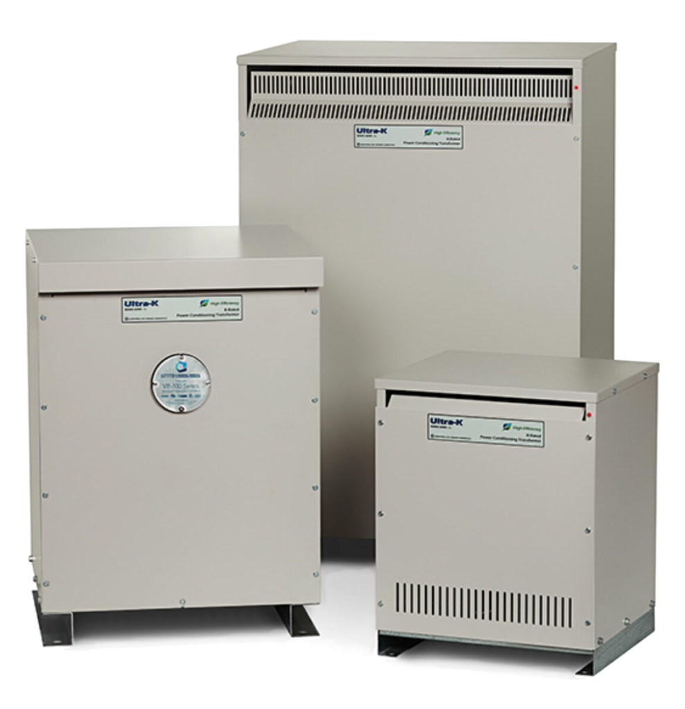
Whether you need a high-efficiency transformer or emergency lighting inverter, our power quality products improve and maintain reliable performance.
Our team is here to support you and solve your power challenges. Connect with our responsive experts today to learn about our customized power solutions and products.